
In this tutorial, we will discuss DBMS architecture, Relational Model Concepts, ER Model
Selecting the correct Database Architecture helps in quick and secure access to this data.
1 tier Architecture : Client, Server, and Database all reside on the same machine.
2-tier Architecture : A two-tier architecture is a database architecture where Presentation layer runs on a client (PC, Mobile, Tablet, etc) and Data is stored on a Server.
3-tier Architecture : This architecture has following layers : 1.Presentation layer (your PC, Tablet, Mobile, etc.) 2.Application layer (server) 3.Database Server
Relational Model Concepts:
- Attribute: Each column in a Table. Attributes are the properties which define a relation. e.g., Student_Rollno, NAME,etc.
- Tables – In the Relational model the, relations are saved in the table format. It is stored along with its entities. A table has two properties rows and columns. Rows represent records and columns represent attributes.
- Tuple – It is nothing but a single row of a table, which contains a single record.
- Relation Schema: A relation schema represents the name of the relation with its attributes.
- Degree: The total number of attributes which in the relation is called the degree of the relation.
- Cardinality: Total number of rows present in the Table.
- Column: The column represents the set of values for a specific attribute.
- Relation instance – Relation instance is a finite set of tuples in the RDBMS system. Relation instances never have duplicate tuples.
- Relation key – Every row has one, two or multiple attributes, which is called relation key.
- Attribute domain – Every attribute has some pre-defined value and scope which is known as attribute domain
What is ER Model?
The ER or (Entity Relational Model) is a high-level conceptual data model diagram. Entity-Relation model is based on the notion of real-world entities and the relationship between them.
ER modeling helps you to analyze data requirements systematically to produce a well-designed database. So, it is considered a best practice to complete ER modeling before implementing your database.
Facts about ER Diagram Model:
- ER model allows you to draw Database Design
- It is an easy to use graphical tool for modeling data
- Widely used in Database Design
- It is a GUI representation of the logical structure of a Database
- It helps you to identifies the entities which exist in a system and the relationships between those entities
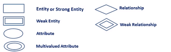
Components of the ER Diagram
This model is based on three basic concepts:
- Entities
- Attributes
- Relationships
WHAT IS ENTITY?
A real-world thing either living or non-living that is easily recognizable and non-recognizable. It is anything in the enterprise that is to be represented in our database. It may be a physical thing or simply a fact about the enterprise or an event that happens in the real world.
An entity can be place, person, object, event or a concept, which stores data in the database. The characteristics of entities are must have an attribute, and a unique key. Every entity is made up of some ‘attributes’ which represent that entity.
Relationship:
Relationship is nothing but an association among two or more entities. Entities take part in relationships. We can often identify relationships with verbs or verb phrases.
| Strong Entity Set | Weak Entity Set |
| Strong entity set always has a primary key. | It does not have enough attributes to build a primary key. |
| It is represented by a rectangle symbol. | It is represented by a double rectangle symbol. |
| It contains a Primary key represented by the underline symbol. | It contains a Partial Key which is represented by a dashed underline symbol. |
| The member of a strong entity set is called as dominant entity set. | The member of a weak entity set called as a subordinate entity set. |
| Primary Key is one of its attributes which helps to identify its member. | In a weak entity set, it is a combination of primary key and partial key of the strong entity set. |
| In the ER diagram the relationship between two strong entity set shown by using a diamond symbol. | The relationship between one strong and a weak entity set shown by using the double diamond symbol. |
| The connecting line of the strong entity set with the relationship is single. | The line connecting the weak entity set for identifying relationship is double. |
Attributes
It is a single-valued property of either an entity-type or a relationship-type.
| Types of Attributes | Description |
| Simple attribute | Simple attributes can’t be divided any further. For example, a student’s contact number. It is also called an atomic value. |
| Composite attribute | It is possible to break down composite attribute. For example, a student’s full name may be further divided into first name, second name, and last name. |
| Derived attribute | This type of attribute does not include in the physical database. However, their values are derived from other attributes present in the database. For example, age should not be stored directly. Instead, it should be derived from the DOB of that employee. |
| Multivalued attribute | Multivalued attributes can have more than one values. For example, a student can have more than one mobile number, email address, etc. |
Cardinality
Defines the numerical attributes of the relationship between two entities or entity sets. Different types of cardinal relationships are:
- One-to-One Relationships
- One-to-Many Relationships
- May to One Relationships
- Many-to-Many Relationships
ER- Diagram Notations
ER- Diagram is a visual representation of data that describe how data is related to each other.
That’s all about DAY-1.


Leave a comment